The structural response is estimated using a combination of analytical expressions and sensoristic measurements. The figure below illustrates a general flowchart within the ROSSINI project demonstrating the flow of input arguments from various sensors, used to identify the seismic shaking through accelerograms and how they eventual pass to the RIE. The accelerometer measurements are processed on a data acquisition board into intensity measures (IMs) to be used with the fragility function database to provide estimates of risk associated with damageable components following the typical lognormal distribution function. This evaluates the risk, or probability, of the actual ds being realized for a given intensity obtained from the sensors.
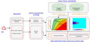
Similarly, the sensors placed around the case study plant will detect actual damage and other types of leakage, which have been described previously. Both evaluation approaches, that is the estimation and actual measurement of notable damage with potential consequences depicted in Figure 5, form the structural part of the RIE Module.
To carry this out, estimates needs to be evaluated for each structural and non-structural component considered within the case study industrial plant. This way, for a given level of shaking detected by the sensors, a real-time estimate of the probability can be obtained by the structural RIE. To enable this, descriptions of damage states and the subsequent consequences of being in a damaged state are provided via the analytical database. This database can be compiled using detailed experimental testing information of the various components encountered, or via representative numerical models that capture the salient features of these structures’ response and potential mechanisms, or via a literature review of similar components available in the literature.
In the ROSSINI project, peak ground acceleration (PGA) and spectral acceleration (SA) were used as IMs for characterizing the fragility functions associated with liquid tanks (see table). Similarly, fragility functions associated with process equipment and pipelines were adapted from available literature. These consequence descriptors and the estimated level of risk they pose will allow for the assignment of indicators, for example wearing a mask within a specific grid. Additionally, each component is assigned to a specific location spatially within the map of the plant. Based on component location, an influence area is identified dependent on its vulnerability, where in case of failure, the influence area will be assigned a risk value and will feed the navigation system described later.
| Component type | Damage State | Consequence |
| Liquid storage tank | Excessive sloshing | Spillage of tank content/sinkage of floating roof |
| Fracture /Yielding of Base Plate | Base plate failure/spillage of tank content (Local collapse) | |
| Yielding of structural shell | Panel joint failure as a result of excessive deformities in the structural shell | |
| Uplifting | Damage to nozzles, causing the release of a potentially harmful substance | |
| Sliding | Damage to nozzles, causing the release of a potentially harmful substance | |
| Elephant foot buckling of shell | Damage to structural shell | |
| Multi-storey precast concrete structure
|
Extensive damage | Severe Damage to Structural Elements and In-Plane Damage of Horizontal and Vertical Panels |
| Near-collapse | Unseating of Precast Beam; Loss of Beam-Column Connection | |
| Collapse | Complete Collapse of Structural System | |
| Non-ductile infilled moment-resisting frame structure
|
Extensive damage | Severe Damage to Structural Elements and In-Plane Damage of Horizontal and Vertical Panels |
| Near-collapse | 30% of load bearing capacity attained with out-of-plane failure of infill panels | |
| Collapse | Complete Collapse of Structural System | |
| Ductile bare MRF structure | Extensive damage | Severe damage to structural elements |
| Near-collapse | 30% of load bearing capacity attained | |
| Collapse | Complete Collapse of Structural System |
Regarding seismic risk values necessary for the ROSSINI navigation system, only the critical damage state (i.e., collapse) of structural components is used in conjunction with the IM value to establish the probability or risk value between 0 and 1 based on the fragility function. Here, 1 stands for non-traversable terrain, while 0 stands for fully traversable terrain. While only collapse of structural components can hinder free movement within the plant, non-structural components pertaining to various toxic material releases or leakages in addition to full collapse may be critical for navigating personnel within the plant to safely exit. The damage states and associated consequences of non-structural components such as liquid tanks as well as structural building typologies described in the table need to be considered for the estimation of different risks. Those risks have various scales and are later combined with structural risk for total risk values associated with a spatially distributed map for navigation instructions.